A bridge that crosses a road, railway or river at an angle looks like a minor variation on a square crossing. It is not. Push a deck off square and the load stops travelling politely down the girders to the nearest support. It twists sideways, concentrates into two corners and lifts at the others. Skew rewrites the conversation between deck, bearings and substructure — and the further you push the angle, the faster the assumptions you inherited from square bridges stop being true.
What skew actually measures
Skew angle is the angle between the line of the support — the abutment or pier centreline — and a line drawn perpendicular to the bridge's longitudinal axis. A square crossing is 0°. Thirty degrees is common where a new structure has to thread over an existing road or rail corridor without moving it. Anything approaching or exceeding 45° is generally treated as heavily skewed and deserves proper attention.
Skew usually exists because something else got there first: a motorway that cannot be realigned, a river channel that must stay where it is, a junction geometry that leaves no room for a square pier line. Whatever the cause, the geometry is fixed early, and it is worth asking at concept stage whether a longer span with less skew would be cheaper overall than a short, sharply skewed deck. That trade is often decided on appearance alone, and it should not be.
How the load path shifts
Think of a square deck as a beam: load runs longitudinally to the nearest support line, and transverse distribution is a secondary effect. A skewed deck behaves more like a parallelogram plate. Load finds the shortest route to a support, and in a skewed geometry the obtuse corners are closer to more of the deck area than the acute ones. The result is a deck that wants to rotate in plan as it bends.
Three consequences follow, and they show up in every skewed job:
- Reactions concentrate at the obtuse corners. The bearing nearest the obtuse corner routinely carries noticeably more than a simple equal-share calculation suggests, while the acute corner reaction drops.
- Uplift becomes possible. Under certain load cases — heavy loading toward one side, temperature effects, or construction stages — the acute corner can go into tension. Bearings that cannot take tension will lift, and the deck will find another, unintended load path.
- Torsion and transverse bending increase. Longitudinal moments often reduce slightly compared with a square deck, which tempts designers into thinking skew is benign. The forces migrate into the edge beams, end diaphragms and cross-frames instead.
That last point matters most for detailing. The end diaphragm in a skewed deck is not a trimming member. It carries real in-plane shear and axial force, and its connections to the girders need to be designed for it.
Bearings, reactions and the substructure
Start with the reactions and be sceptical of them. A grillage or plate model will give you a reaction envelope, but check the shape of it against common sense: total reaction should equal applied load, and the obtuse-corner values should exceed the acute ones under most cases. If your model gives near-equal reactions on a 40° skew, suspect the bearing idealisation.
Then think about movement. Thermal expansion acts along the bridge axis, but at a skewed support that movement resolves into components parallel and perpendicular to the joint. A sliding bearing guided only longitudinally will fight the transverse component. Freed bearings will move in a direction the joint may not appreciate. Either way, the bearing arrangement — guided, fixed, free, or a combination — has to be a conscious decision rather than a default.
On the substructure side, the obtuse corner of an abutment sees higher vertical load and higher bearing pressure. That can drive the pad footing size, the pile group, or the need for a check on sliding and overturning. It is far cheaper to discover this at concept stage than after the foundation has been priced.
Detailing that decides whether the design works
Most skewed bridge problems are detailing problems, not analysis problems. The analysis shows a force; the detail either carries it or does not.
- Bearings: size for the real obtuse-corner reaction and specify uplift restraint where the analysis shows tension. A single small elastomeric pad at a highly skewed corner is rarely adequate.
- Diaphragms: make end diaphragms continuous with the girders and check the connections for the in-plane forces the model reports. Rigid links are fine for sizing girders, not for designing connections.
- Movement joints: skew joints open and close along a raking line, which changes the effective gap, can pinch seals and generates noise as traffic crosses. Check that the joint can accommodate combined longitudinal and transverse movement, and consider whether an integral or semi-integral arrangement removes the problem entirely.
- Edge beams and parapets: they pick up a share of the torsion. Design them as structural members, not as kerb detail.
- Drainage and falls: a crossfall that runs diagonally across a skewed deck needs checking at the low corner, where water will collect.
Where simple assumptions start to wobble
Rules of thumb vary between codes and clients, so treat these as starting points and confirm against the standards you are working to:
- Up to roughly 20°: a grillage with sensible transverse stiffness, or even a wide-beam analogy for simple cases, usually gives results you can defend.
- Roughly 20° to 45°: use a genuine grillage or plate model with realistic bearing and diaphragm stiffness. Simplified live-load distribution factors taken from square-bridge guidance do not transfer reliably.
- Beyond roughly 45°: refine to a three-dimensional shell or solid model, and check construction stages, temperature and accidental load cases explicitly.
Angle alone is a crude measure. A short, wide deck at 30° behaves more awkwardly than a long, narrow one at 40°, because width-to-span ratio governs how much load can travel transversely. Many guidance documents combine the two into a skew index based on the tangent of the skew angle and the deck proportions. Combinations that deserve extra care include skew plus horizontal curvature, skew with slender flexible piers, and integral bridges with skewed abutments, where earth pressure distribution and thermal movement get genuinely complicated.
Practical habits for skewed schemes
Decide the bearing arrangement before you refine the model, because it governs everything downstream. Model diaphragms as members. Check the acute corner for uplift and the obtuse corner for the peak reaction, and do it across the full envelope — construction, temperature, braking and accidental cases included. Sanity-check every reaction diagram once before you trust it. And when the skew passes about 45°, or the deck is short and wide, bring in a second pair of eyes on the modelling assumptions. It is a great deal easier to argue about a bearing layout on screen than about a lifted bearing on site.
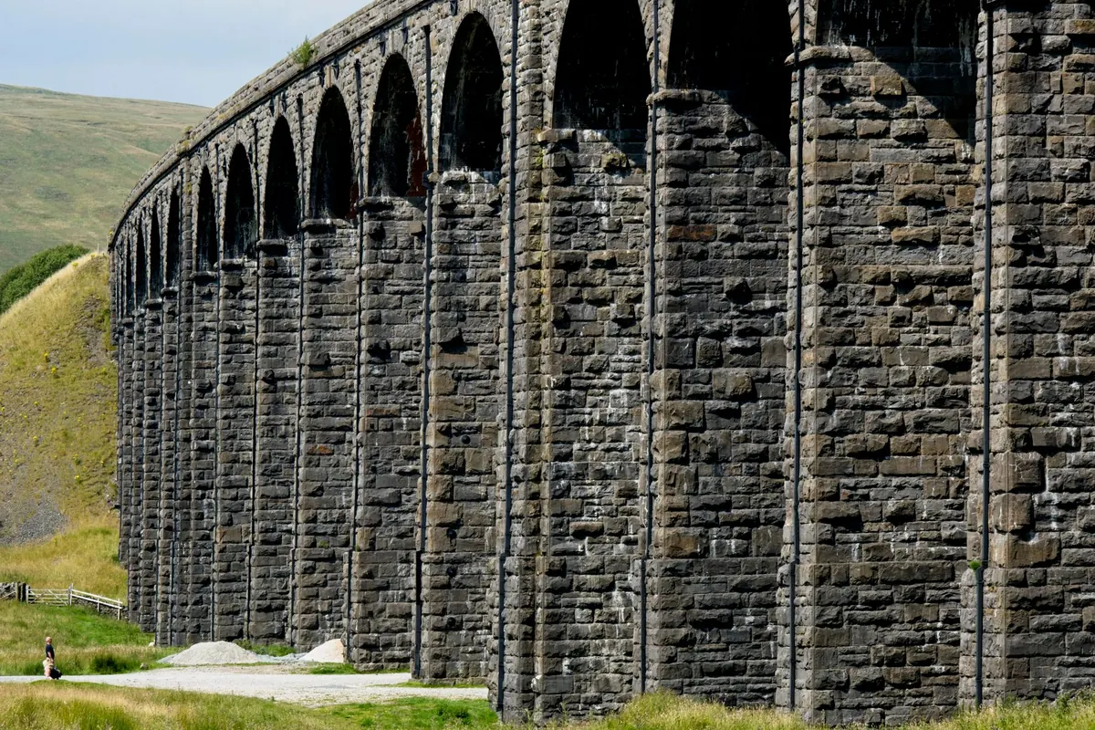
Photo: Michael_Pointner / Pixabay